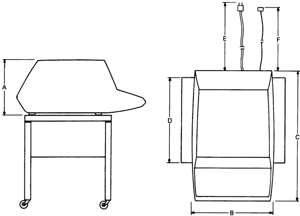
The design of the VT52 will normally pose few constraints on the selection of a place to install the
terminal (Figure 2-1). Extremes of temperature and humidity should be avoided. A summary of the
operating conditions of the VT52 is given in Chapter 1.
Dimensions
Millimeters
Inches
A. Height
360
14.1
B. Width
530
20.9
C. Depth
690
27.2
D. Minimum Table Depth
450
17.2
E. AC Line Cord Length
2438
96.0
F. Interface Cable
*
*
* Total cable length (including the 7.620 meter (25 foot) cable supplied) must not exceed 304.8 meters (1000 feet).
Figure 2-1 Site Considerations
2.2 Unpacking and Inspection
Unpack the unit and place it on the desk or surface where it will be operated.
Inspect the unit for physical damage.
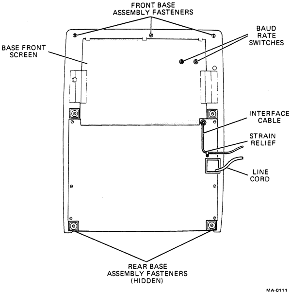
Tip the unit on its back and check the interface cable. It should be fastened to the base with a
strain relief (Figure 2-2).
Check that site power meets the requirements of the terminal. The voltage and power
requirements of the terminal are listed on the ON/OFF switch plate located on the right-hand
side of the unit.
Figure 2-2 VT52, Bottom View
2.3 Installation and Setup
Make certain that the terminal line cord is not connected to an electrical outlet and that the
power (ON/OFF) is in the OFF position.
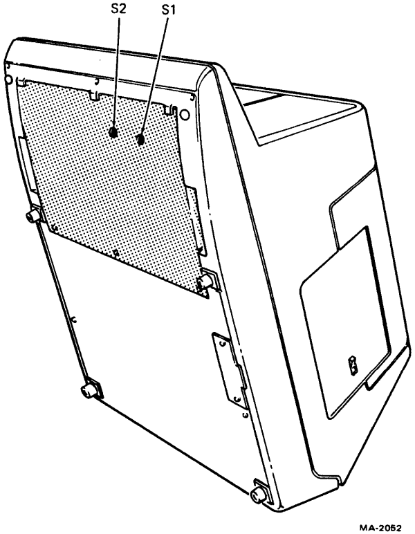
After making certain that there is enough room on the platform on which the terminal is
located, tip the unit back until it is stable. This must be done to gain access to the operator
control switches (Figure 2-3).
Using a screwdriver or small coin, set the switches on the bottom of the terminal to the OFF
LINE and 9600 baud positions (S1 to position 1 and S2 to position G). These switch positions
are shown on the label mounted below the switches.
Return the VT52 to its normal operating position.
Figure 2-2 shows another cable coming from the unit. This cable will have a Mate-N-Lok
connector or an EIA connector, depending on which option you have ordered. Plug this
connector into the I/O port of the computer or modem with which you wish to communicate.
Plug the line cord into an electrical outlet that meets the requirements of the terminal.
Figure 2-3 Operator Control Switch Access Position
2.3.1 Off-Line Tests
Perform the tests described in Paragraphs 2.4.1 through 2.4.6 of the acceptance test procedures.
2.3.2 On-Line Tests
Run the appropriate diagnostic listed in Paragraph 2.4.7 of the acceptance test procedures.
2.4 Acceptance Test Procedures
2.4.1 Flashing Cursor Check
Apply power to the unit by placing the power (ON/OFF) switch to the (ON) position. After a one-half
minute warm-up period, a flashing cursor should appear in the upper left corner of the screen. If
nothing is seen or the display is too bright, reach over and adjust the intensity control on the rear of the
terminal at the top right-hand corner. Control moves to the right for increased brightness.
Check for the terminal to display characters as keys are pressed.
2.4.2 Escape and Control Command Check
Escape and control commands are invoked by:
Pressing the ESC key and then following with a certain character to identify which escape
function is to be performed.
Holding down the CTRL key and simultaneously typing a character to identify which control
function is to be performed.
Notice that the ESC key must only be typed once and then followed by the identifying character; while
the CTRL key must be held down while the identifying character is being typed.
Note the key labeled CAPS LOCK. This key is similar to the SHIFT LOCK key on a typewriter except
that CAPS LOCK will only give you capital letters and will not shift anything other than letters. Keys
with numbers or symbols are not affected by CAPS LOCK. To get the uppercase of these keys, you
must use the SHIFT key. The SHIFT key will also give you capital letters while CAPS LOCK is off.
Miscellaneous
Press "CTRL G"; check for bell to ring
Move Cursor Functions
Press "ESC C"; cursor should move to right; repeat until cursor is in the center of
screen.
Press "CTRL J"; cursor should move down one line.
Press "ESC A"; cursor should move up one line.
Press "CTRL H"; cursor should move left one position.
Press "CTRL I"; cursor should move to the next TAB stop.
Press "ESC I"; cursor should move up one line; this performs a downward scroll if the
cursor was on the top line.
Press "ESC B"; cursor should move down one line.
Press "ESC D"; cursor should move left one position.
Erase Functions:
Type some characters on all 24 lines.
With cursor on the bottom line, press "CTRL M"; check for cursor to move to the
leftmost position on that line.
Press "ESC K"; check for all characters on the bottom line to be erased.
Press "ESC H"; check for cursor to go to the top left of screen.
Press "ESC J"; check for all characters on the screen to be erased.
2.4.3 Terminal Identification Check
Press "ESC Z"; check for the terminal to identify itself with a different character for each VT52
variation:
VT52
"K"
VT52 with Copier
"L"
VT52 with Printer Interface
"M"
2.4.4 Alternate Keypad Mode
Press "ESC =" and check for the terminal to enter ALTERNATE KEYPAD MODE. Numbers typed
on the numeric pad should respond with the following characters:
Key
Character Displayed
.
n
0
p
1
q
2
r
3
s
4
t
5
u
6
v
7
w
8
x
9
y
enter
m
The terminal should exit the Alternate Keypad Mode when "ESC >" is typed. Numbers displayed
should correspond to those numbers typed on numeric pad.
2.4.5 Hold Screen Mode
Place cursor on bottom line.
Press "ESC ["; enters Hold-Screen mode.
Press "LF".
Type "VT52"; characters should not appear on the screen.
Press "SCROLL"; the message "VT52" should now appear on the screen.
Press "ESC \"; exits Hold-Screen mode.
Press "LF"; check for message to scroll up.
2.4.6 Direct Cursor Addressing
Press "ESC H"; cursor should move to the first character position in the first line.
Press "ESC Y" "7" "o"; cursor should move to the last character position on the last line.
Press "ESC Y" "7" "SPACE"; cursor should move to the first character position on the last line.
Press "ESC Y" "SPACE" "o"; cursor should move to the last character position on the first line.
Press "ESC Y" "SPACE" "SPACE"; cursor should move back to the first character position on the first line.
2.4.7 On-Line Acceptance Test
If the VT52 is connected to a DECsystem, run the appropriate VT52 in-house diagnostic for at least one pass.