This chapter provides information used to unpack, pack, and install the VT102. The installation procedure describes how to select the input voltage switch and fuse. The chapter also provides a step-by-step power-up and checkout procedure.
Site Considerations
The terminal consists of a video monitor and a detached keyboard. Figure 7-1 shows their dimensions. The following list covers the terminal’s environmental and power specifications.
Temperature
10° to 40° C (50° to 104° F)
Relative humidity
10 to 90 percent with a maximum wet bulb temperature of 28° C (82° F) and a maximum dew point of 2° C (36° F) noncondensing
Input voltage
99 to 128 Vac (115 V setting)
198 to 256 Vac (230 V setting)
or
87 to 107 Vac (100 V setting)
222 to 268 Vac (250 V setting)
Power consumption
70 W
Power receptacle
Nonswitched, grounded
When installing the terminal, make sure that all power and signal cables are free from stress, sharp bends, or obstructions. Also, make sure to provide access to monitor controls on the back of the terminal.
Several ventilation openings prevent the terminal from overheating. Do not block the air flow around these openings by placing objects on top of or under the terminal. Also, do not allow liquids, coins, paper clips, or other objects to enter these ventilation openings. These objects may damage the terminal.
You can place the terminal on a desk or tabletop. However, operators usually prefer the keyboard at standard typewriter-table height rather than desk height. Terminal tables and stands are available from the DIGITAL Accessories and Supplies Group (A&SG). (See Chapter 10 for more information on accessories).
Position the video monitor to avoid reflected light. The screen should face away from light sources. However, if reflected light is a problem, filter screens are available from A&SG.
For installations with static electricity problems, static mats are available from A&SG.
Figure 7-1 Terminal Dimensions
Unpacking and Inspection Procedure
The terminal is packed in a carton with the following items.
Monitor
Keyboard
AC power cord(s)
SET-UP label
User guide
Programming reference card
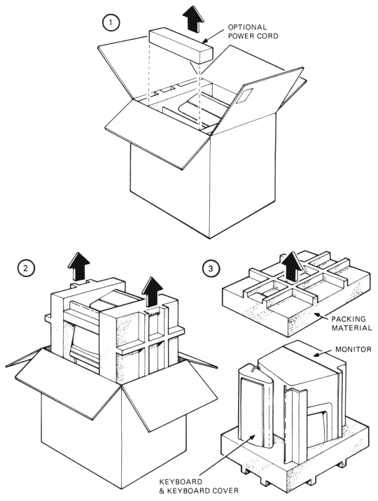
Figure 7-2 shows the terminal’s packaging. Unpack the terminal from the shipping carton by using the following procedure.
Figure 7-2 Terminal Packaging
Cut the carton sealing tape and open the carton flaps.
Lift the non-US power cord out of the carton. This power cord is supplied with some variations of the terminal.
NOTE: All terminals are shipped with a US power cord.
Lift the terminal out of the carton by using the handles in the packing material. Place the terminal and packing on its left side (when facing the front of the terminal).
Remove the packing material on the right side.
Remove the keyboard and keyboard cover, then the monitor from the left-side packing material.
Remove the plastic bags covering the monitor and keyboard.
Inspect the terminal for damage.
NOTE: Notify the carrier and your local DIGITAL Sales Office of any damage.
Install the terminal by using the installation procedure in this chapter.
Packing Procedure
Pack the terminal for shipment by using the following procedure. Figure 7-2 shows the terminal’s packaging. Figure 7-3 shows power switch and cable locations.
Figure 7-3 Power Switch and Cable Locations
Turn the power switch off (0).
Disconnect all cables at the back of the terminal.
Place the monitor and keyboard in plastic bags.
Place the packing material for the left side (facing the front of the terminal) on a flat surface, with the cutouts facing up. Place the monitor in the large cutout.
Route the keyboard cable behind the keyboard. Place the connector in the small cutout.
Place the keyboard cover over the keys, then place the keyboard into the small cutout.
Place the packing material for the right side over the monitor and keyboard.
Place the packaged terminal and power cable in the shipping carton. Fold the carton flaps and tape the carton closed with sealing tape.
Installation Procedure
Install the terminal by using the following procedure. Figure 7-3 shows switch and cable locations.
Perform the unpacking and inspection procedure in this chapter.
Check the terminal for the correct voltage range selection. The terminal can operate with either 120 Vac or 220-240 Vac input power.
CAUTION: Failure to select the proper voltage range will damage the terminal.
A label over the power receptacle indicates the factory-selected input voltage range. Check this label, the voltage selection switch, and fuse for the correct voltage range. Make sure the voltage range matches your local ac power source.
Select 120 volts by performing the following procedure.
Set the voltage selection switch to 115 (operating range 99-128 Vac). On some terminals, the setting is 100 (operating range 87-107 Vac).
Remove the fuse holder cap by pressing in and turning counter-clockwise. Check for a 1.25 A fuse (DIGITAL PN 90-00020-01). Replace the fuse and fuse holder cap by pressing in and turning clockwise.
Select 220-240 volts by performing the following procedure.
Set the voltage selection switch to 230 (operating range 198-256 Vac). On some terminals, the setting is 250 (operating range 222-268 Vac).
Remove the fuse holder cap by pressing in and turning counter-clockwise. Check for a 0.75 A slow blow fuse (DIGITAL PN 12-11237-00). Replace the fuse and fuse holder cap by pressing in and turning clockwise.
Remove the backing paper from the self-sticking SET-UP label and attach to the bottom of the keyboard.
If necessary, install the 20 mA current loop option (VT1XX-CA). Perform the option installation and checkout procedures in Chapter 8.
When using the standard modem connector, selection the internal communication switches. See Communication Switch Selection in this chapter when selecting the communication switches.
NOTE: When using the 20 mA current loop option, the terminal ignores the position of the communication switches.
Place the keyboard in front of the terminal. Plug the keyboard into the keyboard connector.
Connect the communication cable to the terminal. See Communication and Printer Cables in this chapter for more information. Also, see Chapter 6 for information about connector use and signal/pin definitions.
Connect the printer cable to the printer interface connector. See the sections referenced in step 7.
Connect the external video device, such as a video monitor, to the video output connector. The terminal uses a 75-ohm BNC connector. See Appendix A for detailed specifications for this output.
Connect one end of the ac power cord to the terminal and the other end to a nonswitched, grounded receptacle.
NOTE: Make sure the power switch is off (0) before connecting the power cord.
Perform the power-up and checkout procedure in this chapter.
Internal Communication Switch Selection
The terminal has ten internal communication switches to connect or disconnect modem communication lines. See Chapter 6 for more information on these communication lines. Select these switches by using the following procedure.
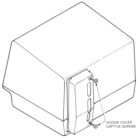
Turn the power switch off (0) and loosen the two captive screws holding the access cover in place (Figure 7-4).
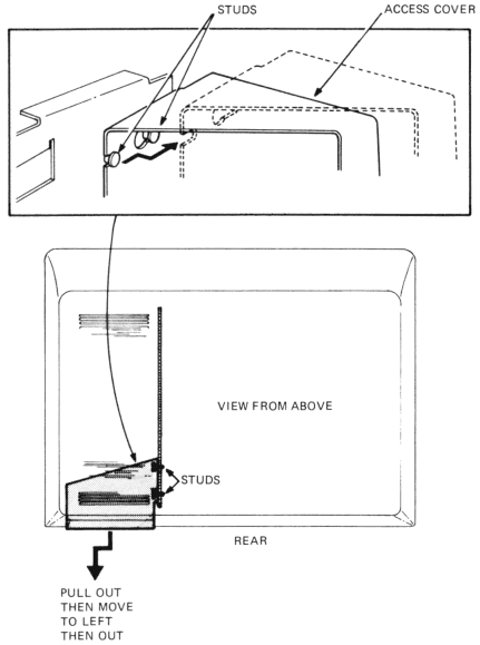
Pull the access cover straight out from the back of the terminal, until loose. Then move the cover to the left, off the supporting studs. Finally, remove the cover by pulling straight out (Figure 7-5).
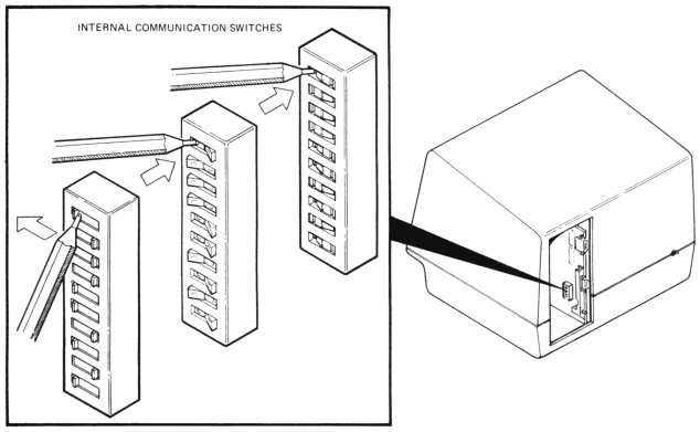
Select the communication switches. The terminal uses one communication switch pack. However, there are three possible types of switch packs used; two types use rocker switches and one type uses slide switches.
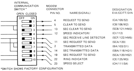
To select the rocker switch, press the side of the switch that corresponds to the desired selection. To select the slide switch, push the switch tab to the side that corresponds to the desired setting. Figure 7-6 shows the location of the communication switches. Figure 7-7 shows the communication lines connected (on, closed) or disconnected (off, open) by these switches.
NOTE: Always use a small-blade screwdriver or ball-point pen to change the communication switches. Never use a lead pencil.
Install the access cover.
CAUTION: You may damage the access cover by tightening the captive screws too much.
Figure 7-4 Access Cover Screw LocationsFigure 7-5 Access Cover RemovalFigure 7-6 Internal Communication Switch LocationsFigure 7-7 Internal Communication Switch Selections
Communication and Printer Cables
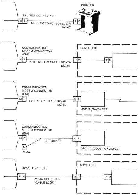
You can order communication and printer cables from A&SG. See Chapter 10 for part numbers and ordering information. Table 7-1 describes each communication cable used, and Figure 7-8 shows connection examples for each cable.
Table 7-1Interface Cables
Part Number
Connector Types
Function
BC22A-10
(10 ft)
RS-232 (female)
to RS-232 (female)
Null modem; connects terminal directly to computer or printer (6-conductor cable).
BC22A-25
(25 ft)
RS-232 (female)
to RS-232 (female)
Null modem; connects terminal directly to computer or printer (6-conductor cable).
BC22B-10
(10 ft)
RS-232 (male)
to RS-232 (female)
Extension; connects terminal to a modem (14-conductor cable).
BC22B-25
(25 ft)
RS-232 (male)
to RS-232 (female)
Extension; connects terminal to a modem (14-conductor cable).
BC03M-xx
(variable length)
RS-232 (female)
to RS-232 (female)
Null modem; connects terminal directly to computer or printer.
BC05D-xx
(variable length)
RS-232 (male)
to RS-232 (female)
Extension; connects terminal to a modem.
BC05F-15
(15 ft)
Mate-N-Lok™
to Mate-N-Lok
20 mA; connects terminal with 20 mA option installed directly to computer. (Supplied with 20 mA option.)
BC05X-xx
(variable length)
Mate-N-Lok
to Mate-N-Lok
20 mA extension
30-10958-02
EIA
20 mA
RS-232 (male)
to RS-232 (female)
and 20 mA (male)
Connects acoustic coupler to terminal EIA or 20 mA.
™AMP, Inc.
Figure 7-8 Cable Connection Examples
Power-Up and Checkout Procedure
A power-up self-test procedure verifies the terminal operation each time you power up. Power up and check out the terminal by using the following procedure. See Figure 7-3.
Turn the power switch on (1). The terminal automatically runs the power-up self-test. The test provides the following indications.
The terminal displays test data, the wait message, then erases screen. (The test data and wait message are not visible if the terminal is not warmed up).
All keyboard indicators turn on and off, and either the ON LINE or OFF LINE stays on. The other indicators may stay on or off, depending on feature selections and received modem signals.
A bell tone sounds.
The cursor appears in the upper-left corner of the screen.
When the power-up self-test finds an error, the terminal provides one of the following indications.
Does not perform the step 1 sequence.
Displays character at the cursor position.
Sounds several bell tones.
See Chapter 9 for more information about self-test failure.
Enter SET-UP to verify a successful test. A SET-UP display should appear on the screen. If not call your local DIGITAL Field Service Office.
If the terminal powers up correctly, select the desired SET-UP features as described in Chapter 3.
After you select the SET-UP features, record the feature selections on the SET-UP label attached to the keyboard.
Save the SET-UP features by using SHIFT and S. See Chapter 3 for more information about saving SET-UP features.