Chapter 4

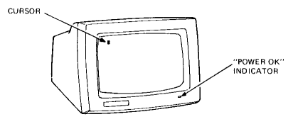
VT200 family terminals perform two functions. First, they act as an input device to the computer, helping you to enter information that is sent to the computer. Second, they simultaneously act as an output device for the computer, displaying data on the video screen. This section describes the controls and indicators found in the VT200 family of terminals.
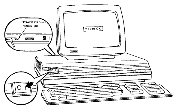
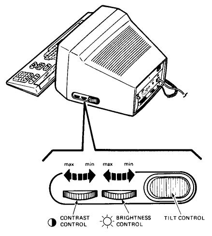
The table below describes the monitor controls and indicators for the VT220 and VT240 Series video terminals.
| Terminal | Indicator/Control | Description |
|---|---|---|
| VT220, VT240*, VT241 | Power OK Indicator | Lights up to indicate that power is on. |
| VT220, VT240*, VT241* | Voltage Selector Switch | Enables the terminal to operate on 120 Vac or 240 Vac. |
| VT220, VT240*, VT241* | Power Switch | Turns power to the terminal on and off. On the VT241 terminal, there is a power switch on both the monitor and the system box. |
| VT220, VT240, VT241 | Contrast Control | Adjusts the contrast of the display screen. |
| VT220, VT240, VT241 | Brightness Control | Adjusts the brightness of the display screen. |
| VT220 and VT240 only | Tilt Mechanism Button | Located on the bottom of the monitor. Used to adjust the angle of the monitor by raising or lowering the rear of the monitor. |
| * These two controls and one indicator are located on the System Box. | ||
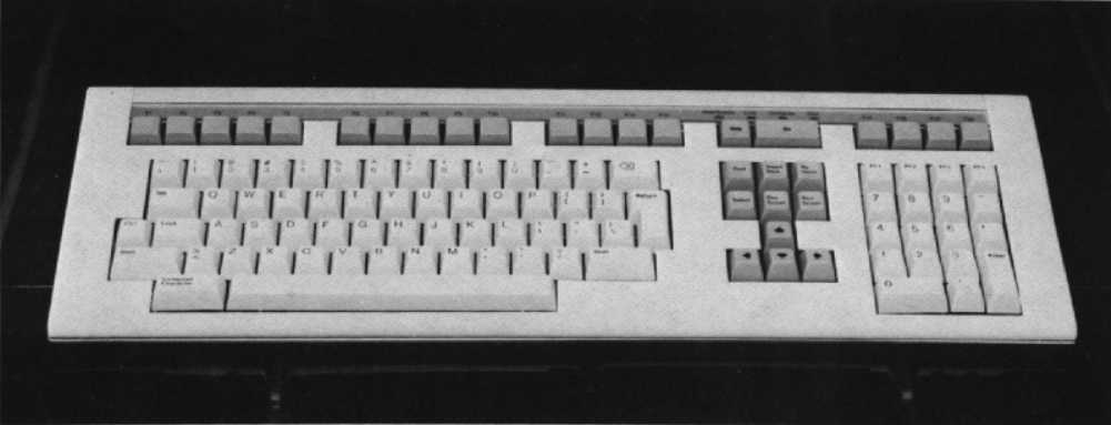
The VT200 family keyboard consists of a main keypad, an editing keypad, an auxiliary keypad, a row of special function keys, four visual indicators, and two audible indicators.

The main keypad operates similar to that of a standard typewriter keyboard. When you press a letter, numeral, or symbol key, the character is sent to the host’s memory and is displayed on the screen. Uppercase letters and symbols are generated when you press the SHIFT or LOCK keys.
| Key | Description |
|---|---|
| Tab | Generates a horizontal tab that normally moves the cursor and the text following it to the next tab stop setting. |
| CTRL | When pressed in combination with another key, the CTRL key causes the terminal to transmit a code that has a special meaning to your system. |
| Lock | When pressed, the LOCK key makes the alphabetic keys generate uppercase characters. When the LOCK key is pressed again, the alphabetic keys generate lowercase characters. |
| Shift (2 keys) | When either the right or left side SHIFT key is pressed, the uppercase function of all keys is enabled. If a key does not have an uppercase function, the SHIFT key will be disregarded. In some cases, this key is used in combination with another key to generate a predefined control function. |
| Return | Transmits either a carriage return (CR) code or a carriage return (CR) and linefeed (LF) code. In some cases, it moves the cursor to the next line when editing text. If NEW LINE was selected in Set-Up mode, RETURN can be a signal to the applications program that a particular operation is finished. |
| Delete | Pressing this key generates a DEL character. Normally, this erases one character to the left of the cursor. |
| Compose Character | This key is used to create special characters, such as , , and , that do not exist as standard keys on your keyboard. Use of this key and compose character sequences are described in detail in the VT220 and VT240 Owner’s Manual. |
The editing keypad consists of four cursor (arrow) keys and six keys directly above them. (See Figure 4-6.) The four arrow keys move the cursor in the direction indicated by the arrow. The six editing keys have functions assigned to them by the applications software in use. See your applications software documentation for details.
This keypad is used to enter numeric data as you would with a standard calculator. In addition, you can assign functions to these keys to be used by the applications software. Again, see your applications software documentation for details.
In some applications, the ENTER key generates either a carriage return or a carriage return and a linefeed. It is also used in Set-Up to select terminal operating characteristics.
Most of the top-row function keys have functions assigned to them by the software in use. Those keys with Digital-defined functions are listed below.
| Key | Description |
|---|---|
| HOLD SCREEN | This key freezes the screen display and stops new characters from being displayed. To “unfreeze” the screen display, just press the key again. |
| PRINT SCREEN | Pressing this key alone stops all screen activity and sends screen text display to the printer. Holding down SHIFT and PRINT SCREEN simultaneously stops all screen activity and sends the screen display to the printer. Holding down CTRL and PRINT SCREEN sets or resets the Auto Print Mode. |
| SET-UP | Pressing this key causes the terminal to go into Set-Up mode. Pressing it while the terminal is in set-up returns the terminal to either the on-line or local mode, wherever it was before you entered set-up mode. |
| DATA/TALK | This key functions only if the integral modem option is installed. It sets the modem to data, talk, or dialer mode. See the VT240 Series Owner’s Manual for details. |
| BREAK | The BREAK key is used to send a break signal. The SHIFT and BREAK keys initiate a disconnect and is the recommended way to disconnect the terminal from the communications line. See the VT220 or VT240 Series Owner’s Manual for details. |
| F11 (ESC) | F11 is normally a function key used by application programs. In VT100 and VT52 modes, it generates an ESC (escape code) character. |
| F12 (BS) | F12 is normally a function key used by application programs. In VT100 and VT52 modes, it generates a BS (backspace) character. |
| F13 (LF) | F13 is normally a function key used by application programs. In VT100 and VT52 modes, it generates an LF (linefeed) code. |
The keyboard has four visual indicators.
The terminal generates a bell tone as part of the power-up self-test. In Set-Up you can enable or disable the margin bell tone, which sounds when the cursor reaches the right-hand margin, and/or a warning bell tone to indicate operator errors.
You can also enable or disable the keyclick sound when in Set-Up mode. This lets you know that the key has been pressed fully. Exceptions to this are pressing SHIFT or CTRL only, and typing when the keyboard is locked.
The VT200 family stores many of its operating characteristics in a nonvolatile memory that retains these settings even when the power is shut off. These operating characteristics can be changed by entering the Set-Up mode. Some characteristics, such as transmit and receive speed, affect communications with the host and printer. These must be set according to the host’s and printer’s requirements. Other characteristics, such as the type of cursor to be displayed, can be set according to your preference. Through the keyboard or the host, you can change all the available Set-Up characteristics to tailor the terminal to your preference.
Set-Up is based on selectable monitor displays called “screens”. Only one screen can be displayed at a time. Each one presents a logical grouping of choices from which you can select terminal parameters.
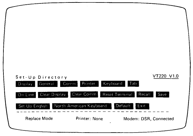
You can even enter Set-Up while you are working in a file without loss of data. The data is redisplayed when you exit Set-Up. Entering Set-Up is achieved by pressing the Set-Up key. The Set-Up Directory screen is displayed immediately. This screen lets you access any other Set-Up screen. It also presents fields you can access to select terminal operating parameters. To select a field, use the arrow keys to position the cursor at the field you want to invoke. Then use the ENTER key to invoke the field.
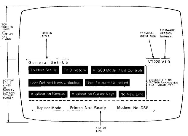
Each screen contains:
During set-up the ENTER key can also do the following:
This is the first of the screens displayed in set-up mode. The Set-Up Directory screen enables you to move through the sequence of Set-Up screens – display, general, communications, printer, keyboard, tab, graphics (VT240 Series only), and Telephone (VT220 and VT240).
It also lets you select the following:
| Field and Field Type | Default | Functions |
|---|---|---|
| Graphics (VT240 Series only) Action |
None | Replaces the Set-Up Directory Screen with the Graphics Set-Up Screen. |
| On Line Parameter |
On-line | Selects on-line or local operation. |
| Clear Display Action |
None | Clears the text on the display that becomes visible when Set-Up is exited. |
| Clear Comm Action |
None | Clears communications by: aborting print operation, escape or control sequence, or device control string processing; clearing keyboard buffers; putting terminal on-line; and sending XON to the host port, if XOFF support is enabled. |
| Reset Terminal Action |
None | Sets many terminal features to a known state. See VT220 or VT240 Series Owner’s Manuals. |
| Recall Action |
None | Replaces all current Set-Up parameters with “saved” values and clears the monitor screen. |
| Save Action |
None | Saves all parameters from the Set-Up screens. |
| Set-Up = Parameter |
None | Selects the language (English, French, or German) in which you want the Set-Up screens displayed. |
| Keyboard Parameter |
None | Selects correct terminal operation for the national keyboard (North American, British, Flemish, Canadian French, Danish, Finnish, German/Austrian, Dutch, Italian, Swiss French, Swiss German, Swedish, Norwegian, French/Belgium, or Spanish) you are using. |
| Default Action |
None | Replaces all current Set-Up parameters with factory default settings and clears the monitor screen. |
| Exit Action |
None | Exits Set-Up and returns the terminal to the operating mode, local or on-line, that was selected in Set-Up. |
The Display Set-Up screen lets you define monitor display characteristics.
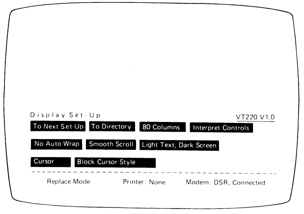
| Field and Field Type | Default | Functions |
|---|---|---|
| To Next Set-Up Action |
None | Replaces Display Set-Up screen with General Set-Up screen. |
| To Directory Action |
None | Replaces Display Set-Up screen with Set-Up Directory screen. |
| __ Columns Parameter |
80 columns | Lets you select 80 or 132 column display. |
| __ Controls Parameter |
Interpret Controls | Lets you select whether control function codes from the host are displayed as characters and not executed or interpreted as controls and not displayed as characters. |
| Auto Wrap Parameter |
Auto Wrap | Selects whether a received character after the right margin is automatically displayed in the first character position on the next line, or overwritten into the last character position on the correct line. |
| Scroll Parameter |
Smooth Scroll | Select the method which lines on the screen scroll up or down. Your choices are smooth, jump, or no scroll. |
| Text, Screen Parameter |
Light text, dark screen | Lets you select a dark screen with light text or a light screen with dark text. |
| Display (VT240 only) Parameter |
Monochrome Display | Selects the color map to operate with monochrome or color monitor, or both (when using both monochrome and color monitors). Note: Color display is available only when you have the color monitor option for the VT240. |
| Text Cursor Parameter |
Cursor | Lets you select whether or not a cursor is displayed in text mode. |
| Cursor Style Parameter |
Block Style | Lets you select block or underline cursor style. |
The General Set-Up screen lets you define a group of general operating characteristics.
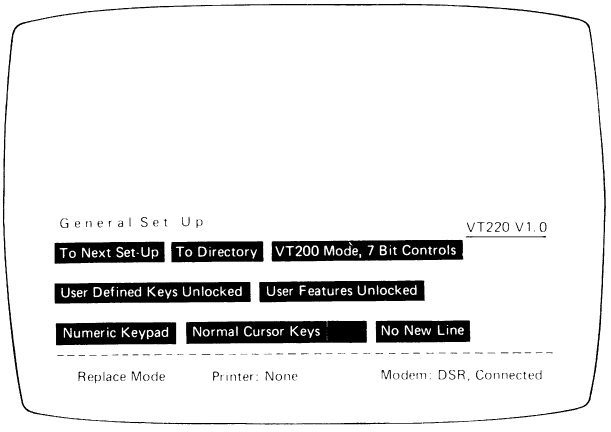
| Field and Field Type | Default | Functions |
|---|---|---|
| To Next Set-Up Action |
None | Replaces General Set-Up screen with Communications Set-Up screen. |
| To Directory Action |
None | Replaces General Set-Up screen with Set-Up Directory screen. |
| Mode Parameter |
VT220 mode, 7-bit controls | Selects the basic terminal operating mode: VT220 mode, 7-bit controls; VT200 mode, 8-bit controls; VT100 mode; VT52 mode, and; 4010/4014 mode (VT240 Series only). |
| VT100 Parameter |
VT100 ASCII | Selects the default character set used in the VT100 or VT52 mode. (ASCII or U.K. characters). |
| User Defined Keys Parameter |
Locked | Lets you select whether or not the host can alter User Defined Key definitions. |
| User Features Parameter |
Locked | Lets you select whether or not the host can alter user-preference features you have set, such as auto repeat, scroll, and screen. |
| Keypad Parameter |
Numeric keypad | Selects whether the keypad transmits ASCII character codes or control codes, used by applications software. |
| New Line Parameter |
No New Line | Lets you select whether the RETURN key generates a carriage return only or a carriage return and a line feed. |
| Cursor Keys Parameter |
Normal Cursor Keys | Normally selected by the host computer. Selects whether the cursor keys transmit ANSI cursor control sequences or application control function. |
The Communications Set-Up screen lets you define the terminal-host communications environment.
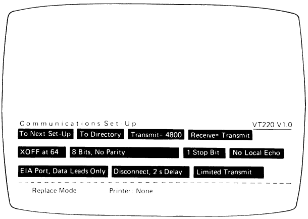
| Field and Field Type | Default | Functions |
|---|---|---|
| To Next Set-Up Action |
None | Replaces Communications Set-Up screen with Printer Set-Up screen. |
| To Directory Action |
None | Replaces Communications Set-Up screen with Set-Up Directory screen. |
| Transmit = Parameter |
4800 | Lets you select the rate (75, 110, 150, 300, 600, 1200, 2400, 4800, 9600, or 19,200 bits per second) at which the terminal sends data to the field host computer. Terminal transmit speed must equal the computer’s receive speed. |
| Receive = Parameter |
4800 | Lets you select the rate (75, 110, 150, 300, 600, 1200, 2400, 4800, 9600, or 19,200 bits per second) at which the terminal receives data from host computer. This must equal the computer’s transmit speed. The terminal, however, can send at one speed and receive at another. |
| XOFF Parameter |
XOFF at 64 | Lets you select the XOFF point or disable the automatic XON/XOFF flow control. Other choices include no XOFF and XOFF at other speeds. VT240 Series values differ from those of the VT220. See VT220 or VT240 Series Owner’s Manuals and VT220 or VT240 Series Programmer’s Reference Manuals for details. |
| Bits, Parity Parameter |
8 bits, no parity | Lets you select the serial character communication format used for communication with the host computer. For other choices, see your VT220 or VT240 Series Owner’s Manuals. This does not set the format for communication with a printer. |
| Stop Bit Parameter |
1 Stop Bit | Lets you select the number of stop bits (1 or 2) used by the host port. This does not set the bits for the printer port. |
| Local Echo Parameter |
No Local Echo | Lets you enable or disable local echo. |
| Port Parameter |
EIA port, Data Leads only | Lets you select the type of port used to communicate with the host. Your choices include: 20 mA port, EIA port with data leads only, EIA port with modem controls, or integral modem (VT240 Series only). See VT220 or VT240 Series Owner’s Manuals and VT220 or VT240 Series Programmer’s Reference Manuals for details. |
| Disconnect, Delay Parameter |
Disconnect, 2 s delay (For all countries except the United Kingdom, which uses 60 ms.) | Lets you enable or disable the disconnect feature and, when modem controls are used, to set the time between when the received line signal drops and disconnection. |
| Transmit Parameter |
Transmit | Lets you limit the terminal transmit speed to between 150 and 180 characters per second, regardless of baud rate. |
The Printer Set-Up Screen lets you define printer operations.
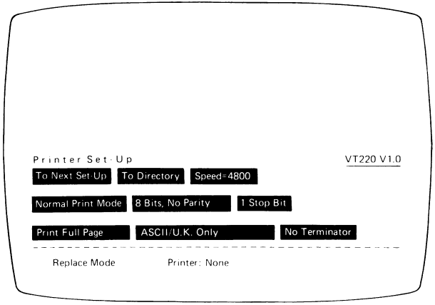
| Field and Field Type | Default | Functions |
|---|---|---|
| To Next Set-Up Action |
None | Replaces Printer Set-Up Screen with Keyboard Set-Up Screen. |
| To Directory Action |
None | Replaces Printer Set-Up Screen with Set-Up Directory Screen. |
| Speed = Parameter |
9600 | Selects the rate (75, 100, 150, 300, 600, 1200, 2400, 4800, 9600, and 19,200) at which the terminal sends data to the printer or auxiliary device. |
| Printer to Host (VT240 Series only) Parameter |
No Printer to Host | Selects whether or not input from the printer or auxiliary device is sent to the host computer. |
| Mode Parameter |
Normal Print Mode | Selects the operating mode – normal, auto print, or controller – for the printer. |
| Bits, Parity Parameter |
8 bits, no parity | Lets you select the character format of the characters used at the terminal printer port. See the VT220 or VT240 Owner’s Manual for details. |
| Stop Bits Parameter |
1 Stop Bit | Sets the number of stop bits (1 or 2) to match those used by the printer or auxiliary device. |
| Print Parameter |
Print Full Page | Lets you select how much of the screen (the full screen or just the scrolling region) is to be printed during a print operation. |
| Printed Data Type Parameter |
ASCII or UK only | Selects the type of characters (from the terminal’s character sets) to the printer. Choose from ASCII or UK only, ASCII or UK line drawing, or all characters. (Only for devices which support Digital’s multinational character set.) |
| Term Parameter |
No Terminator | The print terminator field lets you select what characters come at the end of a print page operation. Selecting Term = FF ends the print page operation with a carriage return, line feed, and form feed. Selecting No Term ends the print page operation with a carriage return and linefeed. |
The Keyboard Set-Up Screen lets you define operating characteristics associated with the keyboard.
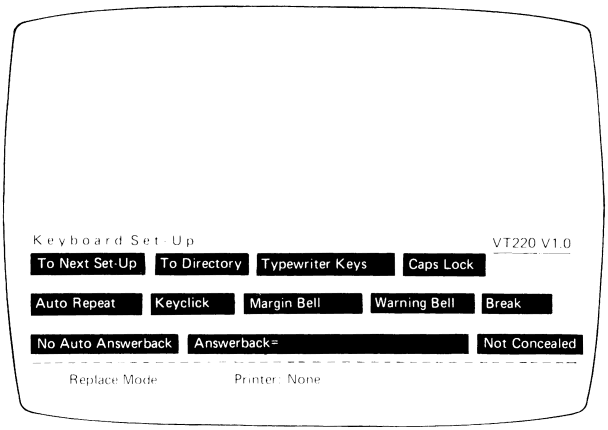
| Field and Field Type | Default | Functions |
|---|---|---|
| To Next Set-Up Action |
None | Replaces Keyboard Set-Up Screen with Tab Set-Up Screen. |
| To Directory Action |
None | Replaces Keyboard Set-Up Screen with Set-Up Directory Screen. |
| Keys Parameter |
Typewriting Keys | Lets you select the appropriate keyboard map for the physical keyboard, either typewriter or data processing. See |
| Lock Parameter |
Caps Lock | Lets you select the way in which the SHIFT and LOCK keys operate. |
| Auto Repeat Parameter |
Auto Repeat | Lets you select whether or not keystrokes are automatically repeated when you hold down a key. |
| Keyclick Parameter |
Keyclick | Lets you select whether or not the keyboard generates a click sound each time a key is pressed. |
| Margin Bell Parameter |
Margin Bell | Lets you select whether or not the terminal generates a bell tone when the text cursor reaches the right-hand margin. |
| Warning Bell Parameter |
Warning Bell | Lets you select whether or not the terminal generates a bell tone on receipt of CTRL G or operating errors. |
| Break Parameter |
Break | Lets you enable or disable the Break function. |
| Auto Answerback Parameter |
No Auto Answerback | Lets you select whether or not the answerback message is automatically transmitted to the host after a communication line connection. |
| Answerback Text Parameter |
None | Provides for user-defined answerback message entry. |
| Concealed Parameter |
Not Concealed | Lets you select whether or not your answerback message is displayable on the Set-Up screen. |
The Tab Set-Up Screen lets you set terminal tab stop setting. Beneath the tab stop fields is a ruler which you can reference when setting tabs. Each tab stop field can show a “T” (tab stop setting) or can be blank (no tab stop setting). You control the tab stop field cursor using the arrow keys. Pressing the ENTER key after you select a field places a “T” in a blank field or removes an existing “T”.
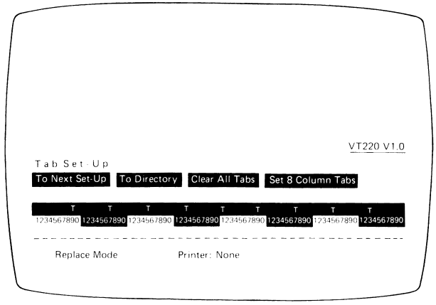
| Field and Field Type | Default | Functions |
|---|---|---|
| To Next Set-Up Action |
None | Replaces Tab Set-Up Screen with Display Set-Up Screen (VT220) or Graphics Screen (VT240 Series). |
| To Directory Action |
None | Replaces Tab Set-Up Screen with Set-Up Directory Screen. |
| Clear All Tabs Action |
None | Clears all previously set tabs. |
| Set 8 Column Tabs Action |
None | Automatically sets tabs every 8 columns starting with column 9. |
The VT240 Series only Graphics Set-Up Screen lets you define graphics parameters for use by your VT240 Series terminal. To set the Tektronix 4010/4014 parameters, refer to the documentation for the applications software you are using.
| Field and Field Type | Default | Functions |
|---|---|---|
| To Next Set-Up Action |
None | Replaces Graphics Set-Up Screen with Display Set-Up Screen or Telephone Set-Up Screen if optional modem is installed. |
| To Directory Action |
None | Replaces Graphics Set-Up Screen with Set-Up Directory Screen. |
| Graphics Cursor Parameter |
Graphics Cursor | Lets you select whether or not the graphics cursor is displayed in graphics mode. |
| Macrograph Report Parameter |
No Macrograph Report | Lets you select whether or not the contents of a macrograph report is sent in response to the ReGIS Report Macrograph Command. |
| 4010 CR Effect = Parameter |
None | Lets you select whether a received carriage return generates a carriage return only or a carriage return and a linefeed. |
| 4010 LF Effect Parameter |
None | Lets you select whether a received linefeed generates a linefeed only or a linefeed and carriage return. |
| Graphics Print Parameter |
Compact Graphics | Lets you select the size of the image on the graphics printer. Invoking compact graphics produces an image that is approximately three-by-five inches. Invoking the expanded graphics choice produces an image that is approximately seven-by-nine inches. |
| 4010 DEL = IMPLIES Parameter |
None | Lets you enable or disable the 4010/4014 “DEL IMPLIES Lo Y” strap option. |
| GIN Terminator = Parameter |
None | Lets you select the characters that follow graphics input (GIN) address transmission – carriage return, carriage return and end of transmission, or no character. |
The Telephone Set-Up Screen is available only if you have selected the optional modem for the VT240 Series terminal. This screen lets you store and display telephone numbers for automatic dialling.
| Field and Field Type | Default | Functions |
|---|---|---|
| To Next Set-Up Screen Action |
None | Replaces Telephone Set-Up Screen with Display Set-Up Screen. |
| To Directory Action |
None | Replaces Telephone Set-Up Screen with Set-Up Directory Screen. |
| Manual Answer/Auto Answer Action |
Manual | With manual answer, the VT240 terminal is in talk mode when disconnected or on power up. With auto answer selected, the terminal is in data mode when disconnected or on power up. |
| Telephone Number A = Text Parameter |
None | Lets you enter a user-defined telephone number to be stored for dialing as designator A. |
| Telephone Number B = Text Parameter |
None | Lets you enter a user-defined telephone number to be stored for dialing as designator B. |
| Concealed Parameter |
Not Concealed | The screen has two Conceal fields. Each one “Conceals” or “Not Conceals” the telephone number entered at the left. Invoking Concealed causes the terminal to replace the telephone number with the text “concealed”. Invoking Not Concealed causes the terminal to display the telephone number as it is entered. |
The VT220, VT240, and VT241 terminals communicate with a host and a printer via full-duplex, asynchronous lines only. There are 10 possible transmit/receive speeds that are selectable in Set-Up. Your VT220 and VT240 Series terminals operate in accordance with the following national and international communications standards and recommendations:
To communicate with the host, the VT220 and VT240 Series terminals use serial character format, which is selected in Set-Up. Digital recommends that the number of data bits be the same for the host port and the printer port. The stop and parity bits, however, can be selected separately for each port.
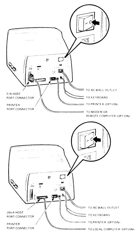
Members of the VT200 family have two asynchronous serial ports: one for communications with a host and another for communication with an auxiliary device such as a printer. The host port has two physical connectors. The EIA or COMM host port connector (EIA RS-232C) connects your terminal to a local or remote host. The 20 mA host port connects your terminal to a local host. The printer port, with a single physical connector (RS-232C/RS-423), connects your printer or another device to your video terminal. On the VT240 Series, the printer port operates as a serial input channel as well. Devices such as digitizers and tablets can be used to input data via this port.
The VT220 and VT240 Series can be directly connected to a local host computer or via telephone lines to a remote host computer. To communicate with a local host, use the 20 mA current loop connector or EIA host port connector using a null modem cable. Connection of the VT220 and VT240 Series to a remote host is made via telephone lines using a modem or acoustic coupler. The modem used at the video terminal end must be compatible with the modem used at the host computer end. The VT220 and VT240 Series accept compatible modems and acoustic couplers such as Bell 103, 113, and 212, including Digital’s DF02 and DF03 modems.
You can locally connect your VT220 or VT240 Series terminal to an asynchronous serial printer using the appropriate cable. Digital’s current printers can be used with the VT220 terminal: LA50 Personal Printer, Letterprinter 100, LQP02 Letter-Quality Printer, DECwriter Correspondent, and DECprinter III. Even Digital’s traditional printers, the LA34, LA35, LA36, and LA38, can be used.
The printer port can be used as a serial input channel or input/output device (VT240 Series), as well as an output device. Choose the mode of operation you want in Set-Up. When the printer port is selected as an input device in Set-Up (Printer-to-Host Mode), data from the auxiliary device, as well as data from the terminal keyboard, can be sent to the host. Data from the printer port is treated the same as keyboard data.
If in Set-Up you select the printer port as an output device (No Printer-to-Host), text and graphics print functions can be initiated from the keyboard as well as from the host. In this mode, input from the printer is disabled.
When the printer port is selected in Set-Up as an input/output device (Printer Controller Mode), the device connected to the printer port is treated as the terminal, while the VT240 transparently monitors line traffic. This means all characters from the host are sent directly to the device connected to the printer port with the exception of XON, XOFF, NULL, and control functions from the host. These functions turn the Printer Controller on and off. All characters from the device are sent directly to the host with the exception of XON, XOFF, and NULL. There is a 256 character input buffer to support input from the printer port. See the VT220 and VT240 Series Owner’s Manuals for more details.
When you VT220 or VT240 Series terminal is properly connected to an appropriate printer, you can locally print whatever is on the monitor screen. To print a monitor screen display that contains only text, press the keyboard PRINT key. This stops all screen actions and sends the information on the screen to the printer. To abort the printing process, just press the PRINT key again.
To print a monitor screen display that contains graphics (VT240 Series only), press SHIFT and PRINT simultaneously. Just as with printing only text, this action freezes the screen and sends all text and graphics information on the screen to the printer. If you want to stop the printing process, press SHIFT and PRINT together.
The VT220 and VT240 Series of terminals operate in one of four text print modes. These modes, selectable in Set-Up, are normal mode, auto print mode, printer controller mode, and local controller mode.
Auto Print mode prints a hardcopy of the current text line before the cursor moves to the next line. The cursor moves to the next line when the terminal receives a linefeed, form feed, or vertical tab. When selected, auto print mode is indicated by a status line in Set-Up. After you have selected Auto Print in Set-Up, invoke the Auto Print mode by pressing the CTRL and PRINT SCREEN keys. To stop Auto Print Mode, press CTRL and PRINT keys again.
Normal print mode lets you select all local printing functions through the keyboard.
Printer Controller Mode gives the host direct control of the printer. Characters received from the host go directly to the printer and are not displayed on the video screen. When invoked, Printer Controller Mode is indicated by a status line in Set-Up. This mode cannot be selected from the keyboard, except by entering Set-Up. Printer Controller Mode does not allow the use of local printing functions, for example, the PRINT SCREEN does not work.
Local Controller Mode is selected by the local and printer controller Set-Up features in the Set-Up Directory. When these features are selected, Local Controller Mode supports keyboard output to the printer. This lets you set up various printers for operation, without involving the host.
The integral modem/auto dialer functions are available if this option is installed. The integral modem/auto dialer function enables you to:
Three modes of operation are available with the integral modem/auto dialer options:
More information can be found in the VT240 Series Owner’s Manual.