Chapter 13

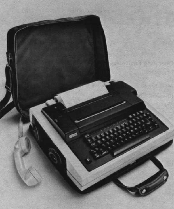
Digital’s DECwriter Correspondent is a plain-paper, dot-matrix teleprinter with the communications power and the reliability that you need to reach the system and get your job done.
The lightweight Correspondent, not much larger than an attaché case, is portable. It combines the printing and forms-handling capabilities of a tabletop terminal with the communications and versatility of a portable teleprinter.
The Correspondent brings your computing power to any of a variety of applications like remote order processing, database information retrieval, and program development.
There are three DECwriter Correspondent models to choose from:
The DECwriter Correspondent’s main features are:
The DECwriter Correspondent offers program-selectable text and graphics modes.
The nine-wire dot-matrix printhead provides high-speed output at the rate of 150 characters per second. By using a nine-wire printhead, the LA12 prints below-the-line descenders, such as in the letters “p”, “q”, and “y”, as well as underlining in all text modes. The Correspondent prints using a bidirectional technique, in which the printhead seeks the shortest distance to the next printable character and skips rapidly over blank spaces. This method reduces computer connection time and telephone connection time, thus reducing costs.
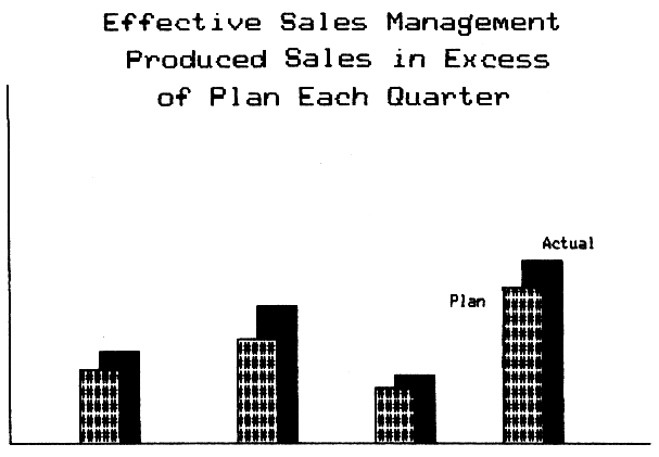
Bit map graphics mode allows for the creation of an infinite variety of pictures and graphs, including bar charts, logos, signatures, and unique characters. Graphics can be integrated with text or data to emphasize points. While the DECwriter Correspondent provides a horizontal resolution of 72 dots per inch, it also lets you select any one of eight vertical resolutions. Check the DECwriter Correspondent Programmer Reference Manual for more details.
A predetermined escape sequence from the host enables the LA12 to enter the bit-map graphics mode. Microcode control of individual printhead wires makes every dot addressable by the host and enables images to be displayed on a video terminal to be faithfully reproduced.
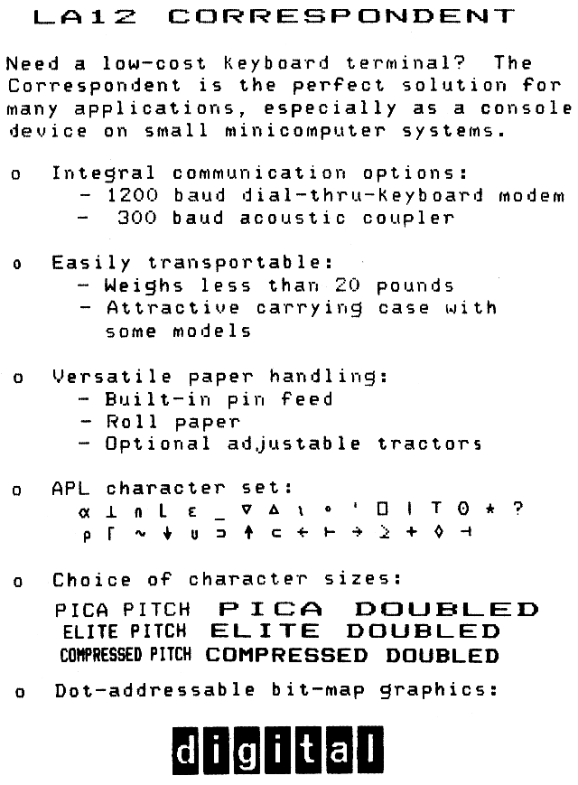
The DECwriter Correspondent has the following operator-selectable character sets resident at all times:
The DECwriter Correspondent can print double-width, compressed, or bold characters via selectable software. Character size can be changed from 10 to 12 characters per inch (pica to elite). In addition, the compressed print displays a full 132 columns for spreadsheet work on standard 21.6 centimeters (8.5 inches)-wide page.
The versatile DECwriter Correspondent can print on single sheets ranging from 7.7 to 21.6 centimeters (3 to 8.5 inches) wide. In addition, roll paper to a maximum width of 21.6 centimeters (8.5 inches) wide can be used, as well as fanfold paper 24.1 centimeters (9.5 inches) wide. It will print on two-part forms where the bond weight ranges between 10 and 20 pounds.
| Part Number | Description |
|---|---|
| LAX12-AL | Adjustable-width tractors. |
| LAX12-RL | Large diameter roll paper holder. |
| LAX12-CL | 20 mA current loop interface. |
| LAX12-HL | International keycaps. |
| LAX12-JL | APL keycaps. |
| LAX12-KL | External numeric keypad. |
| LAX12-U2 | Modem upgrade. |
| LAX12-U4 | Acoustic coupler upgrade. |
The following accessories, supplies and spares are available for the DECwriter Correspondent Printing Terminal (LA12). Check with your sales representative or Digital’s Installed-Base Group for the latest information.
| Part Number | Description |
|---|---|
| LAX12-PC | Paper catcher will accept any 17.6 cm by 27.9 (8.5 in × 11 in) continuous form paper. |
| LAX12-DC | Dust cover |
| STKIT-AA | System Terminal Tool Kit (60 Hz) |
| STKIT-AB | System Terminal Tool Kit (50 Hz) |
| Part Number | Description |
|---|---|
| LA12R-06 | 6 ribbon cartridges |
| LA12R-36 | 3 dozen ribbon cartridges |
| LA12R-A4 | 12 dozen ribbon cartridges |
| Part Number | Description |
|---|---|
| SLA12-00 | LA12 Spares Kit |
The DECwriter Correspondent (LA12) has five different categories of controls and indicators that you use to operate and monitor the terminal. They are terminal controls, the keyboard, visual and audible indicators, and the set-up modes.
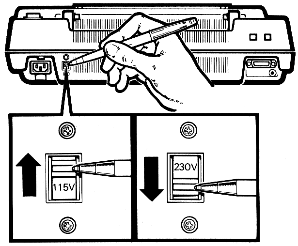
This switch changes the terminal to match the available AC input voltage range. Note: Failure to set the voltage selector switch to the correct voltage range may damage the power supply. The default setting for 120 Vac, 60 Hz.
This switch turns power to the terminal on or off. The on position is labeled “1”, and the off position is labeled “0”.
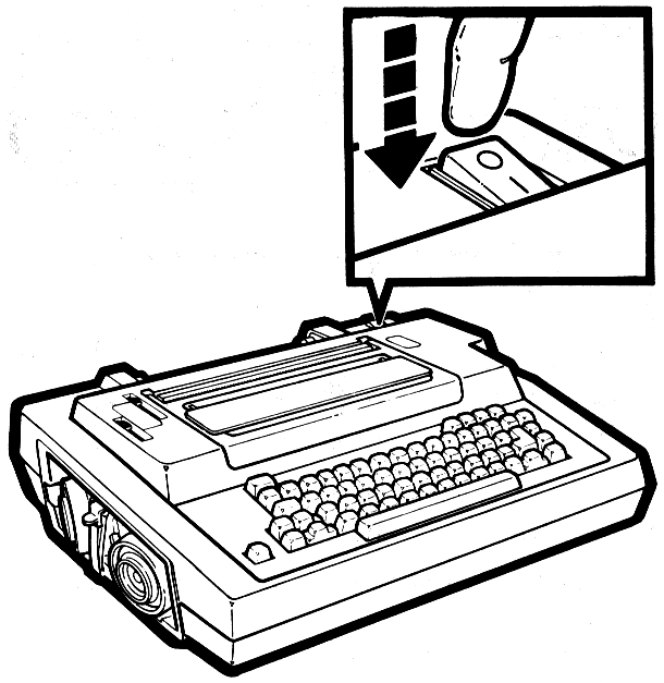
This lever is used to reposition or remove friction feed paper from the terminal.
The bail bar lever is used to hold paper securely against the platen during printing.
The space between the printhead and the platen is controlled by this lever. It enables adjustment of the printhead for clear printing on single or multipart forms.
The ribbon adjustment knob is used to tighten the ribbon when installing a new ribbon cartridge.
The DECwriter Correspondent’s keyboard is arranged like a standard office typewriter and operates in a similar manner. It includes a numeric keypad for rapid entry of numeric data. The keys are grouped into four categories: standard keys, function keys, set-up keys, numeric keypad keys.
The standard keys are standard typewriter keys and include CAPS LOCK and SHIFT. In local mode or when local echo is selected, they operate the same as typewriter keys.
Auto repeat allows for a key that is depressed for more than half a second to sends its code to the computer repeatedly until the key is released. Normally, you would just press the desired key and release it, sending the desired character to the host computer once. All keys will auto repeat except for SETUP, VIEW/RESET, ESC, NUM KEY MODE, HERE IS, LOC FF, BREAK, RETURN, and any key pressed with CTRL.
The CAPS LOCK is a two-position locking key, similar to the LOCK key on a standard typewriter. When it is in the down position, only the alphabetic keys generate uppercase characters, regardless of SHIFT key position. When it is in the up position, the alphabetic keys generate lowercase characters. The numeric, special symbol, function, and numeric keypad keys are not affected by the CAPS LOCK key in either position.
Both of the SHIFT keys cause all standard keys on the keyboard to generate uppercase characters. The SHIFT keys do not affect the function keys or the numeric keypad keys.
The DECwriter Correspondent features over 17 function keys. Some of these keys and their functions are:
These are built into the standard keyboard for use in performing calculator type operations. This function is enabled through the use of the NUM KEY MODE key described earlier. The KEYPAD indicator is on when the numeric keypad mode has been selected. The numeric keypad cannot be activated if the terminal is in SET-UP mode.
The Set-up keys allow you to tailor your terminal’s operation to your needs. The SET-UP key itself lets you enter and exit from Set-Up mode.
The Set-Up keys allow you to:
For more information on how to set up your terminal, refer to the DECwriter Correspondent Operator Guide or to the set-up mode section of this chapter.
When power is applied to the terminal, the visual indicators are on for about six tenths of a second to allow you to check for a bad indicator.
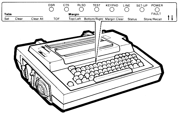
| Indicator | Function |
|---|---|
| Power/Fault Indicator | When power is applied, this light goes on and stays on until the terminal is turned off. If the light is blinking, it indicates a fault in the terminal. |
| Set-Up Indicator | This indicator blinks when the terminal is in set-up mode. The indicator stays on for about 10 seconds when the operator-selected features are being loaded into the nonvolatile memory. |
| Line Indicator | When this indicator is on, the terminal is on-line. When it is off, the terminal is off-line. |
| Keypad Indicator | When this is lit, the numeric keypad is in operation. |
| Test Indicator | When this indicator is on, it means that the terminal is in a self-test mode. |
| RLSD Indicator | When on, the receive line signal detect (RLSD) indicator means the data carrier is present at the terminal input. The state of this indicator is always controlled by the selected communication interface. |
| CTS Indicator | When on, the Clear to Send (CTS) indicator means the terminal is ready to transmit. This indicator will not come on when the acoustic coupler or 20 mA loop interface is being used. |
| DSR Indicator | The Data Set Ready (DSR) indicator tells you when the attached data set is ready for operation. The terminal assumes that the host is already in the nonmodem control mode. |
| Column Indicator | This shows the current position, by column, of the printhead. |
There are two audible indicators in the terminal. A keyclick sound occurs when any key is pressed, if the keyclick feature was selected in set-up. A bell tone, on the other hand, will sound under any of the following conditions:
The corrective action to take for any of these situations can be found in detail in the DECwriter Correspondent Operator Guide.
When selecting a set-up feature, you can choose between using the set-up key and the corresponding function key or typing the appropriate sequence. This section contains brief descriptions of some of the operator-selectable features of the DECwriter Correspondent. These set-up features enable you to prepare the terminal for specific applications. If you require additional information, consult the DECwriter Correspondent Operator Guide or the DECwriter Correspondent Programmer Reference Manual.
The operator-selectable features can only be changed while the terminal is in SET-UP. The suggested sequence to change or select set-up features is:
Set-Up can be entered while in On-Line or Local mode. To prevent the loss of data, take care to enter Set-Up only when the host is not transmitting characters.
    COMMUNICATIONS

    Auto-Ansbk=no
    Buffer=1024
    Comm port=EIA
    Disc-HDX=none
    Echo-local=no
    Fault=xoff(DC3)
    G-HDX= start mode=Rcv
    H-Hi Speed(bps)=1200
    L=Lo Speed(bps)=300
    M-line prot=FDX-data leads
    O-Rcv error ovride=no
    Parity=7/M
    Q-SRTS polarity=Lo
    Restraint=xon/xof
    S-Speed select=Lo
    Turn char=none
    U-power up=line
    V-Frequency=Bell 103

    KEYBOARD

    Auto-linefeed=no
    Break=yes
    C-Keyclick=yes
    Keypad=normal
    Language=USA
    Repeat=yes

    PRINTER

    A-G0 char set=USA
    B-G1 char set=USA
    C-G2 char set=USA
    D-G3 char set=USA
    End-of-line=wrap
    Form Length=264
    G-Print ctrl chars=no
    Horiz pitch (cpi)=no
    NewLine char.=none
    Print Force=hi
    Vert pitch (lpi)=6

    VERSION

    V=V1.2
In order for the terminal to transmit and receive data, the terminal must be compatible with the computer and the communication system. The communication feature selections provide you with the means for matching the terminal and the system.
Some of the communication features available are:
This is actually a response by the terminal to a message sent from the host, so that the terminal can be used unattended. It controls automatic transmission of the answerback message when a communication connection is made. Your choices are on or off.
You can set the buffer size to either 256 or 1,024 characters.
Selects the communications port to be used between the terminal and the computer.
Standard choices vary according to the model you have, and include EIA interface, 300/1,200 b/s Direct Connect Modem (DCM) with keyboard dialing, and 300 b/s Acoustic Coupler Modem (ACM).
Optional choices include 20 mA interface and 300/1,200 b/s Direct Connect Modem (DCM) with keyboard dialing.
When the local echo feature is chosen, every character sent to the computer is also printed by the terminal. If local echo is off, then characters transmitted to the computer are not printed by the terminal.
This selects the action the terminal takes when a fault occurs. Selection of terminal action depends upon the system it is being used with. Three physical faults can be detected and acted upon.
When the cover is open, the Power/Fault light flashes, and printing stops. If the printer is out of paper, the Power/Fault light flashes, and vertical paper motion stops. When the fault is a printhead jam, the Power/Fault light flashes, and any printing stops.
You can choose one of the following choices at any time: no action, send XOFF, short break, or perform disconnect.
When the terminal initiates communication with a computer, the HDX initial calling direction is checked. This direction determines if the terminal starts in the receive or transmit data state. This feature functions only when the EIA port is selected for communication. Consult your DECwriter Correspondent Operator Guide for information on using European modems.
Lets you select either the high-speed or low-speed baud rate operating range. Individual speeds or split speeds can be selected within each range. In some system, transmit and receive speeds are different. The speed selection feature allows you to adapt your terminal to all compatible systems. Note: See the DECwriter Correspondent Operator Guide for more details.
Before choosing an individual baud rate speed, first select high-speed range, low-speed range, or modem selection.
Once you have selected the high-speed or low-speed range, you can now select individual speeds or split speeds in bits per second.
Individual speeds include 50, 75, 110, 134.5, 150, 200, 300, 600, 1,200, 1,800, 2,400, 4,800, 7,200, and 9,600 bits per second.
The split-speed choices are 75 send/600 receive, 75 send/1,200 receive, 150 send/600 receive, 150 send/1,200 receive, 300 send/2,400 receive, 300 send/4,800 receive, 600 send/2,400 receive, and 600 send/4,800 receive.
Modem protocol selection lets you match your system’s communication protocol. You can choose from:
Allows the parity bit of all received characters to either be checked or ignored. This is valuable when the received parity bit is not the same as the transmitted parity bit or when there is no received parity bit.
Selects data bits per character and parity. The data bits per character can be set to 7 or 8 data bits. Parity selects the type of parity bit that the terminal generates for transmitted characters and checks for the received character.
Choices include: no parity, 7 data bits with eighth bit set to mark; no parity, 7 data bits with eighth bit set to space; even parity, 7 data bits; odd parity, 7 data bits; even parity, 8 data bits; odd parity, 8 data bits; and no parity, 8 data bits.
Provides a signal to the computer that is should temporarily suspend data transmission to prevent an overflow in the input buffer. With the DECwriter Correspondent you can choose from among no restraint control, XOFF/XON for restraint control, secondary request to send (SRTS) line for restraint control, and both XOFF/XON and SRTS line for restraint control.
Selects the control character that will be used to turn the line around from being controlled by the computer to being controlled by the terminal, or vice-versa. When the character is received, the terminal controls the communications lines, and when the character is transmitted, the computer controls the lines.
Allows modem operation to be compatible with both U.S. and European communication requirements.
Some features are available to adapt the keyboard to various terminal applications. These include:
| Feature | Description |
|---|---|
| Auto-line feed | Permits RETURN key to generate both a carriage return and a line feed command when desired. |
| Break | Controls operation of the break key. Disables this key to prevent sending a break signal by mistake. |
| Keyclick | Allows you to select whether or not the keyclick will be sounded each time a character keys is pressed. |
| Keypad | The NUM KEY MODE is used to enable operation of the numeric keypad, which is used to perform calculator type operations. |
| Language | Adapts the keyboard to printer operation in different languages. For languages other than the United States, keycaps are required. |
| Repeat | Enables or disables automatic repeating of most key codes when keys are held down. |
Printer features allow you to position a form, set or clear margins and tabs, and select vertical and horizontal pitch. These features can be easily selected through the keyboard by typing in the appropriate escape sequence.
You can select:
The DECwriter Correspondent has the capability of printing only one character set, 94 characters, at a time. In order to allow for a larger selection of printable characters, the characters that can be printed by the terminal are divided into 11 sets – U.S. ASCII, U.K., French Canada, Germany, Sweden, Finland, Norway/Denmark, Italy, Spain, APL, and VT100 Line Drawing. Any of these sets can be selected as the first (G0), second (G1), third (G2), or fourth (G3) printing character set. The computer uses ANSI escape sequences to select the desired set. In order to select a particular character set, you just select one of the following escape sequences.
| Character Set | G0 | G1 | G2 | G3 |
|---|---|---|---|---|
| Britain | ESC ( A |
ESC ) A |
ESC * A |
ESC + A |
| United States | ESC ( B |
ESC ) B |
ESC * B |
ESC + B |
| Finland | ESC ( C |
ESC ) C |
ESC * C |
ESC + C |
| Norway/Denmark | ESC ( E |
ESC ) E |
ESC * E |
ESC + E |
| Sweden | ESC ( H |
ESC ) H |
ESC * H |
ESC + H |
| Germany | ESC ( K |
ESC ) K |
ESC * K |
ESC + K |
| French Canada | ESC ( Q |
ESC ) Q |
ESC * Q |
ESC + Q |
| France | ESC ( R |
ESC ) R |
ESC * R |
ESC + R |
| Italy | ESC ( Y |
ESC ) Y |
ESC * Y |
ESC + Y |
| Spain | ESC ( Z |
ESC ) Z |
ESC * Z |
ESC + Z |
| Finland | ESC ( 5 |
ESC ) 5 |
ESC * 5 |
ESC + 5 |
| Norway/Denmark | ESC ( 6 |
ESC ) 6 |
ESC * 6 |
ESC + 6 |
| Sweden | ESC ( 7 |
ESC ) 7 |
ESC * 7 |
ESC + 7 |
| APL | ESC ( 8 |
ESC ) 8 |
ESC * 8 |
ESC + 8 |
| French Canada | ESC ( 9 |
ESC ) 9 |
ESC * 9 |
ESC + 9 |
| VT100 Special Graphics | ESC ( 0 |
ESC ) 0 |
ESC * 0 |
ESC + 0 |
As your text approaches the right hand margin, you can elect to have the line wrap around to the next line or truncate.
At power-up, the form length is set to 27.9 centimeters (11 inches), corresponding to 66 lines with the default vertical spacing.
The form length command allows you to set the number of lines per page. This is accomplished by using a simple equation to calculate the page length, Pn.
Pn(lines/page) = desired page length (inches/page) × current vertical pitch (lines/inches)
The following chart gives you an idea of some of the more common settings.
| Page Length (Inches) | Selected Vertical Pitch | |||||
|---|---|---|---|---|---|---|
| 2 | 3 | 4 | 6 | 8 | 12 | |
| 3 | 6 | 9 | 12 | 18 | 24 | 36 |
| 5.5 | 11 | 16 or 17 | 22 | 33 | 44 | 66 |
| 7 | 14 | 21 | 28 | 42 | 56 | 84 |
| 8.5 | 17 | 25 or 26 | 34 | 51 | 68 | 102 |
| 11 | 22 | 33 | 44 | 66 | 88 | 132 |
| 14 | 28 | 42 | 56 | 84 | 112 | 168 |
| 21 | 42 | 63 | 84 | 126 | 168 | 252 |
The page length can be set to any length from 1/12 inch per page to 21 inches per page at the selected vertical pitch. If the desired page length exceeds 21 inches, then the printer will default to 21 inches.
You can use the restraint control feature – XON/XOFF to prevent input buffer overflows. When the input buffer receives more characters than a specified upper limit (800 characters), the terminal transmits the selected signal, XOFF, to the host. The host then stops transmitting characters.
As the terminal continues to remove and print characters, the number of characters in the buffer decreases. When the input buffer holds 10 characters, the terminal transmits a second signal, XON, to the host, who then resumes transmission.
This allows you to vary the width of printed characters as well as their spacing (number of characters per inch). You can choose to print 10, 12, 13.2 or 16.5 single-width characters per inch. If you wish to print double-width characters, you can vary the pitch by 5, 6, 6.6, or 8.25 characters per inch.
The horizontal pitch selected determines the maximum column width as per the chart below.
| Horizontal Pitch | Maximum Number of Columns Per Page |
|---|---|
| 5 | 40 |
| 6 | 48 |
| 6.6 | 52 |
| 8.25 | 66 |
| 10 | 80 |
| 12 | 96 |
| 13.2 | 105 |
| 16.5 | 132 |
The horizontal-margins sequence sets the left and right margin. If both parameters are not zero, and the first parameter is smaller than the second on, then the left margin will be set to the first parameter, while the right margin will be set to the second parameter. Note: Changing the horizontal pitch modifies the horizontal margins.
A horizontal tab is a preselected point on a line to which the printhead advances when a horizontal tab control character is received. The DECwriter Correspondent has 132 possible horizontal tabs stops, one for each column. These tab stops are associated with column numbers, not physical positions on the paper. Thus, as was the case with horizontal margins, changing horizontal pitch will also change the physical position of tab stops.
With the DECwriter Correspondent, you can select either normal printing, or for greater emphasis, bold printing.
For your application, it may be desirable to disable the paper out switch. With the DECwriter Correspondent, you can select this feature.
Normally, when the paper-out switch detects that you are about to run out of paper, it stops printing about one inch from the end of the page. If your application requires printing to the very end of the page, you can use the paper-out override.
Selecting the proper print force for your application is another feature provided by the DECwriter Correspondent. Multipart forms require a high print force. This ensures that each copy is as clear and legible as the first. A low print force is better for single copies. By using the low force, your printhead lasts longer, and printing is quieter.
This allows you to vary the number of lines per inch. You can select to use 2, 3, 4, 6, 8, or 12 lines per inch.
You can set top and bottom vertical margins with this feature. The top vertical margin specifies the first printable lines, while the bottom vertical margin specifies the last printable line. When vertical pitch and form length are changed, the vertical margins must be reset.
A vertical tab is a preselected line to which the printhead advances when a vertical tab control character is received. The printer has 168 vertical tab positions. Vertical tabs can be set and cleared like horizontal tabs. Vertical tab stops are associated with specific line numbers, not physical positions on the paper. Thus, changing vertical pitch changes the printing position of the vertical tabs on the paper.
The DECwriter Correspondent terminal features are contained in three memories – operating, user permanent, and default.
The terminal operates according to the features entered in the operating memory. You can change a feature in the memory by entering SET-UP and changing the feature. The operating memory features are horizontal and vertical pitch, margins, and tabs, form length, and printer character sets.
User permanent memory is used to store operator selected features. The computer cannot change the features stored in this memory. You can change them by entering SET-UP, changing the feature, and performing a store procedure. User memory features can be loaded into operating memory by performing a recall procedure. When a recall procedure is performed, all the features previously stored in operating memory are erased.
Default memory contains the typical selections for each SET-UP feature. These are stored in the permanent memory and cannot be changed by the operator.
The DECwriter Correspondent (LA12) uses escape sequences standardized by the American National Standard Institute (ANSI) to control many of its features. These escape sequences provide additional controls that are not provided by the control characters in the character set. These sequences are multiple-character control functions are not printed, but are used to control printing and processing of characters.
Detailed information on escape sequences can be found in the DECwriter Correspondent Programmer Reference Manual or in Appendix H at the end of this book.
The DECwriter Correspondent requires no preventative maintenance other than surface cleaning. You can clean the external surfaces and platen with a damp cloth. Do not use excessive water or cleaners with solvents. Rubbing the keycaps with a dry or barely moist cloth is enough to clean them. Note: Do not remove the keycaps for cleaning; damage to the switch contacts can occur if the keycaps are not replaced correctly.
The terminal covers are not meant to be weatherproof. There are several openings in the covers through which liquids, coins, paper clips, and other objects can fall. Metal objects will disturb the electronic operations of any terminal if they come within contact of the circuitry. For this reason, it is recommended that you do not place drinks or metal objects on any part of the terminal.
The ventilation slots on the top and bottom of the terminal should be kept clear to prevent overheating.
The DECwriter Correspondent offers a selection of self-tests. A power-up and printer self-test occur automatically when the terminal is turned on. These provide an initial visual indication of terminal operation. The other tests can be keyboard-operated for further testing of terminal operation from set-up mode.
Other tests include:
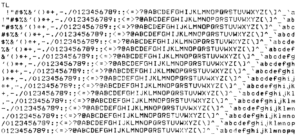

The Correspondent also features a Self-test Help Message that shows the necessary keystrokes for any of the terminal self-tests. To see this message, enter set-up mode, type “T” and press RETURN. This will enable you to initiate a self-test procedure.
If your printer is not operating, chances are the problem is minor and you can correct it yourself. Listed below are some of the common problems, their probable cause, and the corrective action that you can take. Note: Always turn off the printer before you attempt to correct a problem.
No response when power switch is turned on (set to 1). LED indicators are off. Carriage does not move.
Power/Fault light flashes. (No bell tone sounds.)
Power/Fault light flashes. (Bell tone sounds.)
No printing, carriage moves.
Print is too light.
Print density impression drops off.
Print density randomly varies across the page.
Prints light-to-dark, or dark-to-light.
Missing dots on any printable character (always in the same row).
Missing dots only on some characters.
Prints incorrect characters.
No line feeds.
Improper line feeds (inconsistent vertical motion).
Print line slanted in friction feed.
Print line slanted in pin-feed application.
Any one character does not print.
Printer prints NVM err during store procedure or recall procedure.
No key codes transmitted (EIA operation). Local operation is normal.
Prints double characters.
Acoustic coupler test fails.
Acoustic coupler test passes but there is no communication.
Direct connect modem test fails in analog loopback mode.
Direct connect modem test fails in remote data loopback mode.
The following documents contain more detailed information about the DECwriter Correspondent (LA12).
Also of interest are:
| Print speed | 150 char/s (text) |
| Print technology | Bidirectional, dot matrix |
| Print density | 7 × 9 (text) |
| Character pitch | 5, 6, 6.6, 8.25, 10, 12, 13.2, 16.5 char/in |
| Line spacing | 2, 3, 4, 6, 8, or 12 l/in |
| Graphics | 144 or 180 dots/in, horizontal 72 dots/in, vertical |
| Line feed speed | < 50 ms/l at 6 l/in |
| Buffer Capacity | 200 or 1,024 characters |
| Buffer Control | XON/XOFF or restraint signal data synchronization |
| Type | Single sheet, roll or fanfold |
| Dimensions | Single sheets: 7.6 to 21.6 cm (3 to 8.5 in) wide Roll: 21.6 cm (8.5 in) maximum width Fanfold: 7.6 to 21.6 cm (3 to 8.5 in) wide |
| Baud Rates | 50, 75, 110, 134.5, 200, 300, 600, 1,200, 2,400, 4,800, 7,200, 9,600 |
| Split speeds | 600 or 1,200 receive with 75 or 150 transmit; 2,400 or 4,800 receive with 300 or 600 transmit |
| Data interface | Serial RS232-C and RS423 EIA standard |
| Data interface options | Bell 103/212 Direct Connect Modem, Bell 103 Integral Acoustic Coupler, 20mA |
| Parity | 7-bit, odd, even, mark, or space 8-bit, odd, even, or none |
| Voltage | 120 or 240 Vac, switch selectable |
| Frequency | Range of 47 to 63 Hz |
| Power consumption | 55 W, maximum during printing |
| Heat dissipation | 188 BTU/hr |
| Temperature | 10°C to 40°C (50°F to 104°F) |
| Relative Humidity | 10% to 90% |
| Width | 46.4 cm (18.3 in) |
| Depth | 39.4 cm (15.5 in) |
| Height | 14.4 cm (5.7 in) |
| Weight | 8.2 kg (18.0 lb) |