The Digital VT320, like the VT200 Series before it, allows character glyphs to be created and sent to the terminal as a Dynamically Redefined Character Set (DRCS). In this way you can use up to 96 custom character shapes on the screen at one time. These extra characters can be used to provide letter shapes that are missing from the built-in sets, or they can even be used to pretend that the terminal has a graphics capability.

In 80-column mode, the VT320 displays characters in a matrix 15 pixels wide by 12 pixels high. In 132-column mode, this drops to 9 pixels wide by 12 pixels high. However, each pixel has a rather extreme aspect ratio, making it nearly three times as high as it is wide. Vertical lines of only one pixel wide will tend to disappear on the screen. For this reason, the built-in glyphs have vertical strokes three pixels wide.
Downloading the font to the terminal is accomplished with the control sequence DECDLD:
DCS Pfn ; Pcn ; Pe ; Pcmw ;
Pw ; Pt ; Pcmh ; Pcss { Dscs
Sxbp1 ; Sxbp2 ; ... ; Sxbpn ST
DCS is the 8-bit control code Device Control Sequence, which can be represented by
the 7-bit sequence ESC P. ST is the 8-bit control code String Terminator,
which can be represented by the 7-bit sequence ESC \.
The DECDLD parameters are detailed in the table below, taken directly from Installing and Using the VT320 Video Terminal (EK-VT320-UU).
| Parameter | Name | Description | |||||||||||||||||||||||||||
|---|---|---|---|---|---|---|---|---|---|---|---|---|---|---|---|---|---|---|---|---|---|---|---|---|---|---|---|---|---|
| Pfn | Font number | Selects the DRCS font buffer to load.
The VT320 has one DRCS font buffer. Pfn has two valid values, 0 and 1. Both values refer to the same DRCS buffer. |
|||||||||||||||||||||||||||
| Pcn | Starting character | Selects where to load the first character in the DRCS font buffer.
The location corresponds to a location in the ASCII code table.
Pcn is affected by the character set size. (See Pcss below.) In a 94-character set, a Pcn value of 0 or 1 means that the first soft character is loaded into position 2/1 of the character table. In a 96-character set, a Pcn value of 0 means the first character is loaded into position 2/0 of the character table. The greatest Pcn value is 95 (position 7/15). |
|||||||||||||||||||||||||||
| Pe | Erase control | Selects which characters to erase from the DRCS buffer before loading the
new font.
|
|||||||||||||||||||||||||||
| Pcmw | Character matrix width | Selects the maximum character cell width.
If you omit a Pcmw value, the terminal uses the default character width. Any Pcmw value over 15 is illegal. Use Pcmw values 2 through 4 with VT220 compatible software. Remember that VT220 fonts appear different VT320. Fonts designed specifically for the VT320 should use values 5 through 15. |
|||||||||||||||||||||||||||
| Pw | Font width | Selects the number of columns per line (font set size).
|
|||||||||||||||||||||||||||
| Pt | Text or full-cell | Defines the font as a text font or full-cell font.
Full-cell fonts can individually address all pixels in a cell. Text fonts cannot individually address all pixels. If you specify a text cell, the terminal automatically performs spacing and centering of the characters. |
|||||||||||||||||||||||||||
| Pcmh | Character matrix height | Selects the maximum character cell height.
Pcmh values over 12 are illegal. If the value of Pcmw is 2, 3 or 4, Pcmh is ignored. |
|||||||||||||||||||||||||||
| Pcss | Character set size | Defines the character set as a 94- or 96-character graphic set.
The value of Pcss changes the meaning of the Pcn (starting character) parameter above.
|
|||||||||||||||||||||||||||
Dscs defines the character set name. It consists of from one to three
characters. The last
character of the name is a character in the range ‘0’ to ‘~’ (3016 to 7E16).
There can be from zero to two name characters preceding this one, in the range SP to ‘/’
(2016 to 2F16). This name will be used in the Select Character Set (SCS) sequence.
For example, if you call the new set ‘!!P’, the following sequence will designate it into G0. G0 is
mapped into GL by default, so the characters from the new set will be displayed when the terminal
receives codes in the range ‘!’ to ‘~’ (2116 to 7E16):
ESC ( !!P
Because the terminal can hold only one DRCS at a time, there is no particular advantage in preferring one name over another. However, you may wish to provide a character set with a name that will be used by an existing application, in which case the name would be already decided. For example, the VT420 is supplied with a character set called DEC Technical, which has the name ‘>’. If you want to use this set on the VT320, you could download it and use your application unchanged.
It is possible to give your set the same name as one of the built-in sets. In this case, your definitions override the internal ones until your set is superseded by another downloaded set or the terminal is reset.
The definitions for each glyph follow immediately on from the character set name. The characters are defined by a number of sixels, which are groups of six vertical pixels encoded as one ASCII character. Each character definition consists of a set of up to 15 sixels for the top six pixel rows, followed by a ‘/’ (2F16), followed by the sixels for the bottom six pixel rows. Character definitions are separated from each other by semicolons (‘;’, 3B16).
The mapping from a group of six vertical pixels into a sixel character is quite simple. The pixels can be read as a binary number, with the top pixel being the least significant bit. In other words, we say that the top pixel has a value of 1 if it is on or 0 if it is off. The second pixel down has a value of 2 if it is on or 0 if it is off. Each subsequent pixel has twice the value of the one above it, so that the sixth pixel has a value of 32 if it is on and 0 if it is off. Add the value of the pixels together, which gives a number between 0 and 63 inclusive. This is converted to a character code by adding 63, which is the code of the question mark character, ‘?’. The correspondence between each possible combination of six pixels and its sixel character is illustrated below.

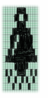
 I used to define soft characters with an editor that I wrote for the VAX. However, I occasionally
drew characters on graph paper and coded them by hand. If you do this, remember the aspect ratio
of the pixels, nearly 3:1. I’ve drawn the character on the left, which is supposed to be
a ringing bell. We’ll convert this image into sixels.
First, we take the top six rows of pixels. The first column contains no black pixels, so its value is sixel character from the table above is ‘?’. The same is true of the next two columns. In column four, the lowest two pixels are black (lit), so the sixel character will be ‘o’. The alternative way of working this out is to read the these pixel rows as a binary number as described above and add on 63, the ASCII code of ‘?’. Reading these pixels as a binary number, we get 1100002 = 4810. Adding 63 to this gives us 111. The character with ASCII code 111 is ‘o’.
If we continue this for the entire top row, we get the fifteen sixel values ???owYn||~ywo??.
The bottom row gives us the sixel values ?IRJaVNn^NVbJRI.
If we send the following sequence of characters to a VT320 in 80-column mode, it will define a character set called ‘P’ and place the bell in the first position. (The spaces in this example are just for clarity; don’t type any spaces.)
ESC P 1;1;1;0;0;2;0;0 { P ???owYn||~ywo?? / ?IRJaVNn^NVbJRI ESC \
Our bell can now be accessed by designating character set ‘P’ into G0, which is mapped into GL by default, so that sending the character ‘!’ (2116) to the terminal will produce our new character instead of an exclamation mark. We’ll send a plain exclamation mark to the terminal first to show the difference.
! ESC ( P !
If all has gone well, you should see the image below on the screen.
