Digital VT320 Serial Connections
The VT320 terminal has three serial connections on the back. There are two 6-pin MMJ
connections, and a 25-way D-type connector. Some U.S. models of the VT320 don't have
the 25-way D-type. This document describes these connectors.
Modified Modular Jack (MMJ) Connections
The VT320 has two MMJ connectors, one for host connections, marked with two arrows,
and one for printers with serial interfaces. These connections are physically and
electrically identical.
Physical Interface

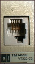
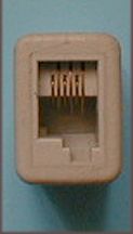
 The leftmost picture shows the host connector on the back of the VT320. The printer
connector is identical (though the icon above is different). The picture on the right shows a Digital H8572 adapter end-on.
This adapter has two MMJs, for joining lengths of terminal cable. Despite the difference in
appearance, they both receive the same shape plugs.
The MMJ and its complementary connector, the Modified Modular Plug (MMP), have an
offset tab at the bottom to make sure that they can't be confused with U.S. telephone
connections, which have a centred tab. Telephone connections in the U.K. use sockets
which are different from both the U.S. design and the MMJ.
The pins in these sockets are numbered from pin 1 on the left to pin 6 on the right.
Electrical Interface
Digital designates the electrical interface as DEC-423. This is a superset of the
EIA RS-423-A standard[1], with better filtering
and tighter level tolerances. Digital claim reliable data communication with unshielded
cables over much greater distances than EIA-232 allows, typically 300m. DEC-423 is
compatible with EIA-232 interfaces for connections employing data lines only.
The signals on these pins are described in the table below, lifted directly from
EK-VT320-UU-001, Installing and Using the VT320 Video Terminal.
6-Pin DEC-423 Comm and Printer Interface Signals
| Pin |
Signal |
Mnemonic |
Description |
| 1 |
Data terminal ready |
DTR |
From VT320
When on, tells the modem or printer that the VT320 is ready to send or receive. |
| 2 |
Transmitted data |
TXD+ |
From VT320
Sends serial characters. Held in the mark state (-) when characters are not being sent.
In modem control modes, sends data only when DSR and DTR signals are on. |
| 3 |
Transmit signal ground |
TDX- |
Provides the common ground reference potential for transmitted signals TXD+ and DTR. |
| 4 |
Receive signal ground |
RXD- |
Provides the common ground reference potential for received signals RXD+ and DSR. |
| 5 |
Received data |
RXD+ |
To VT320
Receives serial characters. |
| 6 |
Data set ready |
DSR |
To VT320
For the comm line: When on, tells the VT320 that the modem is in the data mode and is ready to communicate.
For the printer line: Receives DTR on this line. If DSR is present at power-up, the printer controls
print operations. If DSR is not present at power-up, the terminal checks for DSR before
each print operation. |
25-way D-sub Connection
The VT320 provides a second host connector. The Communications Set-Up page has
a setting called Host Port Selection which allows use of either the MMJ or this port.
The VT320 is a single-session terminal, so only one can be used at a time, though the
MMJ printer connector can be used with either type of host connector selected.
Physical Interface
The second host connector is provided on VT320s is a male 25-way D-type subminiature
connector.
Electrical Interface
This interface operates in accordance with EIA RS232-C. The table below is also
taken directly from Installing and Using the VT320 Video Terminal.
25-Pin RS232-C Comm Port Interface Signals
| Pin |
Signal |
Mnemonic |
EIA/CCITT/DIN |
Description |
| 2 |
Transmitted data |
TXD |
BA/103/D1 |
From VT320
Sends serial characters. Held in mark state when characters are
not being sent.
In modem control modes, sends data only when RTS, CTS, DSR, and DTR signals are on. |
| 3 |
Received data |
RXD |
BB/104/D2 |
To VT320
Receives serial characters. In modem control modes, ignores
characters if RLSD signal is off. |
| 4 |
Request to send |
RTS |
CA/105/S2 |
From VT320
When on, places the modem in transmit mode. |
| 5 |
Clear to send |
CTS |
CB/106/M2 |
To VT320
When on, tells the VT320 that the modem is ready to send. |
| 6 |
Data set ready |
DSR |
CC/107/M1 |
To VT320
When on, tells the VT320 that the modem is in data mode and is
ready to exchange RTS, CTS and RLSD signals. |
| 7 |
Signal ground |
SGND |
AB/102/E2 |
Serves as common ground reference potential for all connector signals, except
protective ground. |
| 8 |
Receive line signal detect (carrier detect) |
RLSD |
CF/109/M5 |
To VT320
When on, tells the VT320 that the signal received on the
communication line is good enough to ensure correct demodulation of received data.
When off, indicates no signal received, or signal is unsuitable for demodulation. |
| 12 |
Speed indicator |
SPDI |
CI/112/M4 |
To VT320
When on, enables a modem to control the terminal's transmit and
receive speeds. Sets the speed to 1200 bits per second, regardless of set-up selection. |
| 20 |
Data terminal ready |
DTR |
CD/108.2/S1.2 |
From VT320
When on, tells the modem that the terminal is ready to send
or receive. |
| 23 |
Speed select |
SPDS |
CH/111/S4 |
From VT320
When on, tells the modem that the receive speed selected in
set-up is greater than 600 bits per second. |
Other Resources
1 The Telecommunications
Industry Association (TIA) web site is the place to look for the latest versions of
EIA/TIA standards. At the time of writing (October 1998), the latest versions of EIA-232
and EIA-423 were:
- Interface Between Data Terminal Equipment (DTE) and Data Circuit-Terminating
Equipment (DCE) Employing Serial Binary Data Interchange (ANSI/TIA/EIA-232-F-1997), and
- Electrical Characteristics of Unbalanced Voltage Digital Interface
Circuits (ANSI/TIA/EIA-423-B-1995).
EIA was the Electronic Industries Alliance, until ceasing operations in 2011.

 The leftmost picture shows the host connector on the back of the VT320. The printer
connector is identical (though the icon above is different). The picture on the right shows a Digital H8572 adapter end-on.
This adapter has two MMJs, for joining lengths of terminal cable. Despite the difference in
appearance, they both receive the same shape plugs.